What are they really?
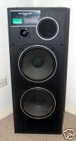
The units are badged Sansui, but I have my doubts. From the amount of damage
to the grills and cabinets, they had seen a few parties, and not surprisingly,
the tweeters were open circuit. The speakers stand about 1 meter tall,
are constructed from particle board, not MDF, have little internal damping
material, contain two 10" paper coned woofers and a horn tweeter. One woofers
cone was coming away from the surround in a small section.
Dismantling the units showed the woofers to be marked Plessey/Foster
C250L24 7ohm and the tweeters to be Plessey/Foster H016N41 8 ohm
and the enclosure to be a 70 liter bass reflex with a round vent
of 98mm diameter, 100 mm long. The crossover network was:-
The center woofer is actually connected via a high pass filter, and
note that no inductors were used. The upper woofer is actually being used
as a midrange, yet it isn't isolated from the woofer chamber.
The 10" woofers
The damaged driver cone surround join was repaired with a contact cement
and all cleaned up. The woofer's Thiele-Small parrameters were then measured
to see how suitable the enclosures really were. This was done using the
sine generator in
TrueRTA, an 8 ohm 100watt series resistor,
a power amplifier and a Digital Multimeter. The values were put in an Excel
spreadsheet.
Vas was determined using the added weight method, by
sticking 15gms of Blu.tack on the cones, and determining
the Resonance Frequency again.
The linear plots of the Resonance Frequencies are:-
The power amplifer used in taking the measurements has a low frequency
rolloff from 20Hz, and that accounts for the low end dip in the above plots.
These values and others determined with the DMM are then fed into:-
The woofers end up having :
Fs = 44Hz
Qms = 3.51
Qes = 0.75
Qts= 0.62
Vas = 96 liters
That isn't particularly impressive for a 10" driver. They don't have
much magnet and are lighter than a comparable unit today. It does mean
they have more top end, making the 2 way system feasable.
Theoretical Low End Response
Putting these numbers into Speaker Workshop results in a
low end plot of the box to be like:-
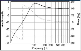
This doesn't take into account that the upper woofer isn't actually
being driven at low frequencies, and may physically be in series with the
other woofer, but electrically it isn't. An undriven driver will act something
like a passive radiator, in addition to the port. Note that the roll off
is quite steep. Doesn't look like you will get much bass from this.
If we use the box as is and use a single 10" driver, the result looks
something like:
This has less of a peak, a gentle slope and an extra half an octave,
at least, of bass extension.
Measured Low End Response
If we measure the woofer response, in the original 2 woofer system, with
pink noise and a microphone very close to the dust cap we get the following.
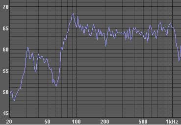
This shows a very steep roll off from 90 Hz, and a big dip at 60 Hz.
This doesn't take into account the effect of the port. The undriven middle
woofer has put a big hole in the low end, but it comes up again at 30 Hz.
If we measure the single woofer system, by removing the midrange/woofer
and replacing it with a 18mm MDF cover,
we get:
This unsmoothed plot isn't taking into account the effect of the port.
The mic is only flat to 32 Hz, so ignore the plot under that. The RadioShack
Analog Sound Level Meter on the C setting is used for signal level and
low end and midrange plots. A RTA mic calibration file has been used.
With a slightly different mic and speaker set up, the following shows
the close mic'ed port and single woofer system responses.
The result is a usable response to under 40 Hz, and no funky dip like
the original. The cabinet needs some internal bracing, and we will add
more damping material. BoxNotes shows that some peaks and dips correspond
to cabinet resonances.
There is more too it than just frequency response thought. Transient
response and distortion are important too. May be later..
The low end of the system sounds better with a single woofer in each
box, and that is how we will renovate them. The originals were designed
by marketing...
Myth Busted.
The High End
Dismantling a tweeter showed that the voice coil/dome assembly was open
circuit. Foster is now called Fostex, but I couldn't find a reference for
this tweeter, even though other part numbered units looked similar and
have replacement parts available.
Replacing them was the simplest solution. All that requires
is physically mounting them, designing a suitable cross over network, and
doing all that testing and listening....
The RadioShack SPM has no usable response over 10 kHz, so a custom preamp
and a electret mic insert is pressed into service. The mic insert used
only has a response to 15 kHz, and it isn't flat, but it will do for these
investigations.
The close mic'ed pink noise response of a Jaycar CT2010 8 ohm soft dome
tweeter, when driven by the existing 3.3uF bipolar electrolytic is:
This isn't a bad match for the single woofer, and results in just a
slight dip at about 2.5k Hz. We need to do a bit more work yet. The tweeter has a resonance at around 1kHz that must be avoided.
Higher order cross-over networks and woofer impedance compensation is required.
Home
Copyright © 1995-2009 Art & Technology. All rights reserved. Sydney Australia.
No reproduction is permitted without explicit written permission.
|
|


